Introduction
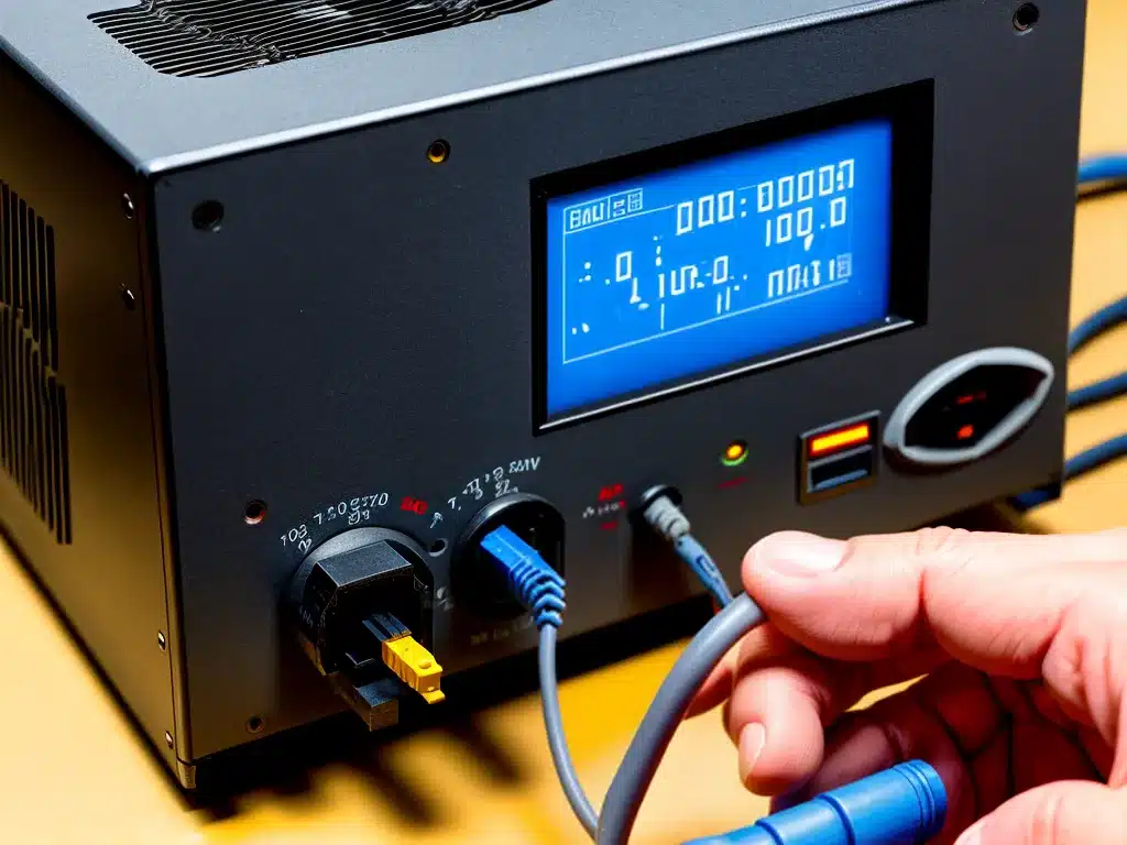
Testing a power supply for faults can seem daunting to someone without electrical experience. However, with some basic knowledge and tools, anyone can diagnose common power supply issues. In this guide, I will walk through the step-by-step process to test a power supply and determine if it has any faults.
Safety Precautions
Before testing a power supply, I take a few safety precautions:
-
Unplug the power supply from the outlet and from the device it is powering. This prevents electric shock while testing.
-
Discharge capacitors by shorting the power supply pins with a screwdriver. Capacitors hold dangerous charges even when unplugged.
-
Use insulated tools like an insulated screwdriver to avoid contact with live circuits.
-
Wear safety glasses in case capacitors explode. High voltage capacitors can hold charge for a long time.
-
Work in a clear area without clutter to avoid accidental contact with live terminals.
Required Tools
Testing a power supply requires some basic tools:
-
Multimeter – Measures voltage, resistance, and continuity. An autoranging digital multimeter is ideal.
-
Insulated screwdrivers – For safely discharging capacitors and probing test points.
-
Load device – A 12V bulb, small motor or resistor to connect as a load to the power supply during testing.
-
Test leads – For connecting the multimeter to test points.
-
Soldering iron (optional) – Handy for resoldering any loose solder joints if needed.
Visual Inspection
I start by doing a visual inspection of the power supply:
-
Check for any damaged components like bulging/leaking capacitors, burnt resistors etc. This can indicate a short circuit or component failure.
-
Look for discolored or burnt spots on the printed circuit board. This points to localized overheating.
-
Verify solder connections are intact. Reflow any cold solder joints.
-
Clean the board with isopropyl alcohol to remove dust, dirt and debris.
Any issues found during inspection should be addressed before proceeding with further testing.
Testing the Outputs
With the power supply unplugged from the outlet, I use the multimeter to test the output voltages:
-
Set the multimeter to DC voltage mode.
-
Connect the black probe to any ground pin of the power supply.
-
Connect the red probe to each power output pin one by one and verify the voltages match the expected values. For example, +5V, +12V, -12V etc.
-
A significant deviation (+/- 10%) indicates a fault in the corresponding voltage regulator.
-
No output could mean a blown fuse or faulty transformer.
Load Testing
To thoroughly test the power supply, I connect a suitable dummy load and then power it up:
-
An automotive tail light bulb works well as a load for 12V supplies.
-
For lower voltage logic supplies, a resistor or small motor can be used.
-
Monitor the output voltages under load using the multimeter. A healthy supply maintains regulation under load.
-
Check if the fan is spinning. Faulty fan operation points to issues with the fan voltage rail.
-
Listen for abnormal noise like humming or whining coils. This indicates a problem.
-
Verify the outputs remain steady during testing. Fluctuations can signify a faulty component.
-
Smell for burning smells from stressed components. Unplug quickly if there is an odor.
Isolation Testing
For further in-depth testing, I perform isolation checks on the power supply:
-
Test for continuity between the AC input pins and output pins using the multimeter.
-
There should be no continuity between input and output. Any reading indicates an isolation breakdown.
-
On switch mode supplies, verify continuity between primary and secondary coils of the transformer. A short indicates a faulty transformer.
-
Check resistance to ground from all pins – it should show an open circuit rather than a short to ground.
Proper isolation is critical for safety. If isolation checks fail, the power supply should not be used until it is repaired and re-tested.
Summary
Systematically testing a power supply involves:
-
A visual inspection to look for damaged traces, bad solder joints, leaking capacitors etc.
-
Verifying all output voltages with a multimeter. Voltages should be within 10% of expected values.
-
Load testing with a dummy load and checking regulation under load. Listen for abnormal noises.
-
Isolation testing using continuity and resistance checks to confirm input-output separation.
With basic tools like a multimeter and a dummy load, and taking appropriate safety precautions, I can thoroughly test a power supply for proper functioning as well as electrical isolation. This prevents damage to electronics by providing clean and stable power.


